Crossed-helical and worm gear pairs are a common type of plastic gears, employed in several actuators, ranging through different industries (automotive, house appliances, medical). The motion transmission principle of such gear pairs enables very high transmission ratios in one single stage, which offers high power transmission density. This article provides a comprehensive overview of known failure modes and the available state-of-the-art models for conducting design rating procedures of plastic worm and crossed helical gears.
Introduction
Crossed-helical and worm gear pairs are a common type of plastic gears, employed in several actuators, ranging through different industries (automotive, house appliances, medical). The motion transmission principle of such gear pairs enables very high transmission ratios in one single stage, which offers high power transmission density. Due to favorable tribological properties of plastic materials they can run in dry conditions for a short duration and under low load, while for transmitting higher powers and for longer operation they usually run in grease-lubricated conditions. Despite the fact that such gears are very commonly used, there has been comparatively limited research done on their performance characteristics.
Data on how different plastic materials perform in a worm gear transmission is almost non-existing. The majority of applications are designed based on an empirical know-how and by employing conservative methods leading to over-dimensioning. This offers a great opportunity for further improvements of the design methods, enabling a much higher material utilization. This article provides a comprehensive overview of known failure modes and the available state-of-the-art models for conducting design rating procedures of plastic worm and crossed helical gears.
1 Worm Geometry Variants
Several variations of worm gear drives exist, each offering distinct advantages and disadvantages. The possible combinations are schematically shown in Fig. 1 and include:
- Cylindrical crossed-helical gear pair
- Cylindrical worm paired with enveloping (globoid) worm wheel
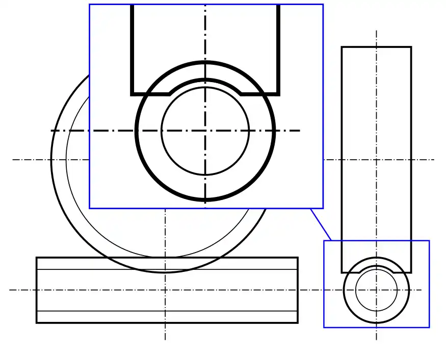
- Cylindrical worm paired with semi-enveloping (semi-globoid) worm wheel
- Enveloping worm paired with cylindrical worm wheel
- Enveloping worm paired with enveloping worm wheel
The most common type is the cylindrical crossed-helical gear pair, where both the “worm” and the “worm wheel” are cylindrical and hold a helical lead profile. This simple design is relatively straightforward to manufacture also using plastic processing methods like injection molding. The main drawback of this gearing geometry is that it results in a theoretical point contact during meshing and consequently offers a lower load-carrying capacity due to a less favorable load distribution across a small contact area on the active flank.
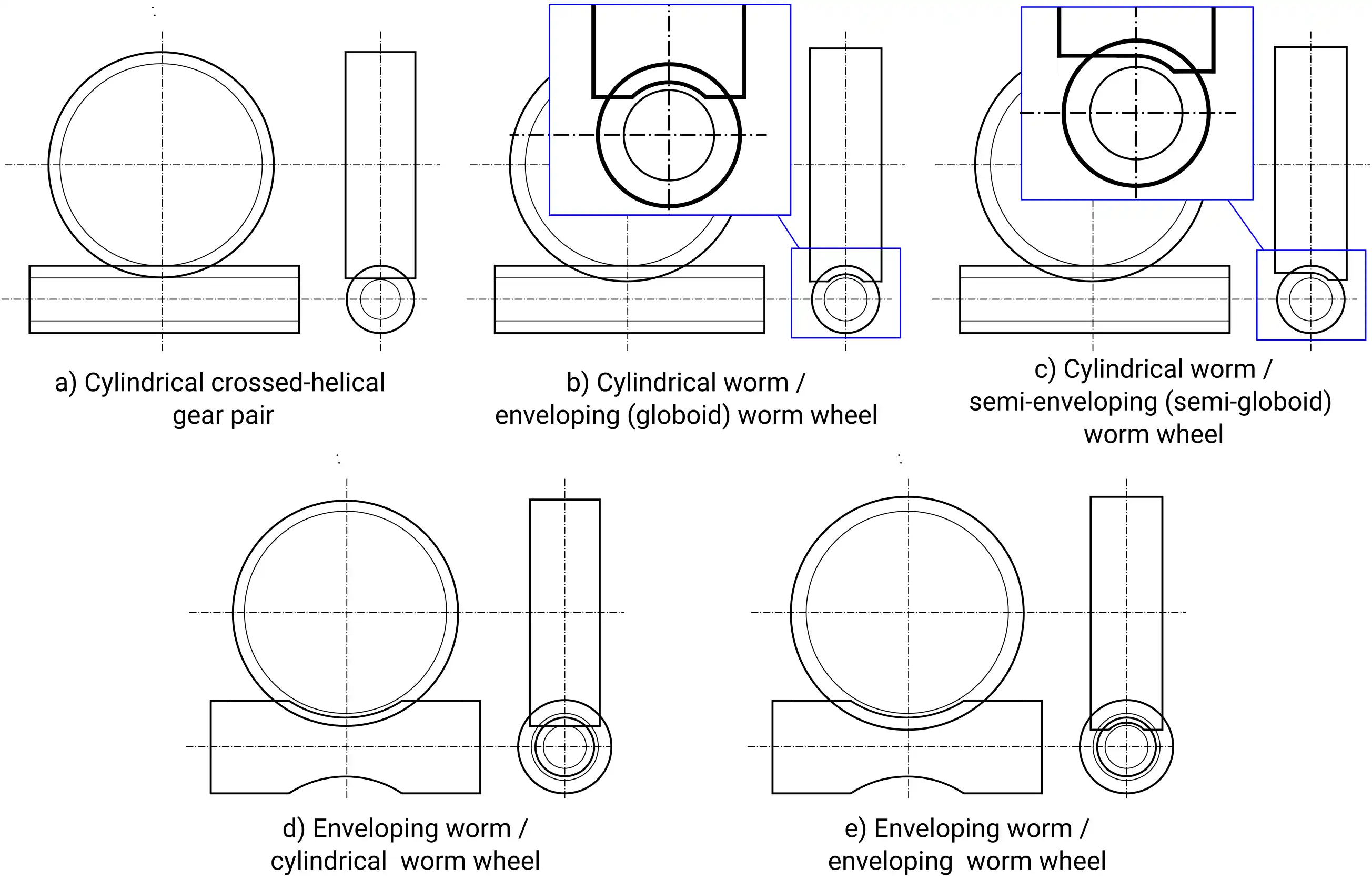
Fig. 1: Available crossed helical and worm gear geometry configurations.
For improved load-carrying capacity, durability and smoother operation, enveloping worm gears can be produced. This design offers an improved line-contact load distribution, potentially leading to reduced wear and a longer service life. Two main variations exist: cylindrical worm / enveloping (globoid) worm wheel and enveloping worm / cylindrical worm wheel. In the former, the worm wheel has a curved profile, matching the worm’s curvature of the helix, which prolongs the path of contact. The latter features a curved, hourglass-shaped worm gear meshing with a straight-toothed worm wheel. Both offer improvements over the basic cylindrical pair, but the cylindrical worm / globoid worm wheel generally boasts the highest efficiency due to its deeper tooth engagement. On the other hand, both geometries increase the complexity and cost of production.
A globoid worm wheel is especially problematic for plastic injection molding since it exhibits negative draft angles, which hampers the possibility for part ejection from the molding tool. To amend this problem, a semi-enveloping (semi-globoid) worm wheel geometry can be introduced that provides partial line contact and avoids negative draft angles that undermine part ejection in the globoid geometry.
Finally, the least common variant is the enveloping worm / enveloping worm wheel. Both the worm and the worm wheel have curved profiles, maximizing tooth contact and achieving the best load distribution among all these designs. However, these benefits come at the cost of increased manufacturing difficulty as already discussed above.
Our further analysis will entirely be based on cylindrical crossed-helical gear pairs, since this geometry is by far the most commonly used in plastic worm gear drives and the VDI 2736: Part 3 guideline also provides calculation methods for this type of gear pair. To simplify communication, in subsequent sections the words “worm” and “wheel” will be used to denote the pinion and gear of the analyzed crossed-helical gear pair.
2 Failure Modes and Load Carrying Capacity Evaluation of Plastic Worm Gear Drives
Plastic worm gear drives are commonly designed by employing a metal worm in pair with a plastic wheel. Plastic worms, although viable, are used less often due to complexities involved in injection molding and much lower achievable load carrying capacity and service life compared to metal variants. In this regards, available design guidelines and standards, like the VDI 2736: Part 3 [1] further discussed in the following sections, also focus primarily on the evaluation of plastic worm wheels. The design of this type of worm wheels involves a durability control against the most commonly experienced failure modes during gear running (Fig. 2). In general, there are various failure modes that can, depending on the materials, loads, and lubrication conditions, occur on plastic worm wheels [2], including:
- Thermal failure
- Root fatigue failure
- Flank fatigue failure
- Pitting
- Wear
- Viscoplastic tooth deformation
These are in essence the same types of failure modes exhibited by cylindrical (parallel-axis) plastic gears. However, there are certain differences in the way these failure modes manifest and their probability of occurrence. In the following sections the main failure modes will be presented in more detail, with methods of durability evaluation and experimental characterization further discussed.
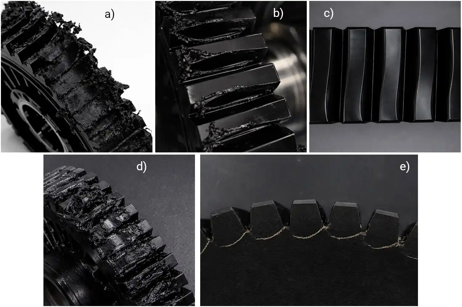
Fig. 2: Examples of various failure and damage modes exhibited on polymer worm wheels – a) thermal overload, b) wear, c) tooth deformation, d) tooth fatigue fracture and e) root fatigue fracture.
2.1 Standards and Guidelines for Load-Carrying Capacity Evaluation
In the past few decades there has been a gradual evolution in worm and crossed-helical gear design standards. The already noted VDI 2736: Part 3 guideline for plastic crossed-helical gear pairs has its foundation in the DIN 3996 standard, which covers the calculation of load-carrying capacity of metal worm gears. The standard covers calculation methods for pitting resistance, wear load capacity, worm shaft deflections, tooth root strength, and thermal stability [3]. The standard has undergone revisions, with the 2012 and 2019 versions reflecting updates in calculation methods and material properties. Based on the DIN 3996 standard, the ISO/TR 14521:2010 [4] standard was formed, which provides calculation methods for assessing wear, pitting, worm deflection, tooth breakage and temperature in metal cylindrical worm gears. The standard was withdrawn and replaced in 2020 by the ISO/TS 14521 [5,6], which covers the same failure modes but omits sections related to worm gear geometry and instead references to the standard ISO 10828:2024 [7] for geometry specifications.
In the field of non-metal gears, the precursor of the VDI 2736: Part 3 guideline is the VDI 2545 [8], which was withdrawn in 1996. The 2545 version includes a root stress carrying capacity evaluation method, which was also deemed suitable for use in crossed-helical cylindrical gears and is still proposed in modern gear design software. In the VDI 2736: Part 3 guideline no comparable root strength rating method is presented and instead a fatigue fracture model dependent on the nominal shear stress on the active flank is defined. Since the VDI 2736: Part 3 guideline currently constitutes the state of the art in plastic worm gear rating models, it will be considered in more details in subsequent sections.
2.2 Worm Gear Load-Carrying Capacity Evaluation According to VDI 2736: Part 3
The guideline enables the evaluation of the load carrying capacity of plastic worm wheels and durability against several key failure mechanisms, typically exhibited by these components during running. A schematic presentation of the complete worm wheel evaluation procedure per noted guideline is shown in Fig. 3. As visible, the complete evaluation procedure is composed of several steps and failure mode criteria, described more in detail in the following pages.
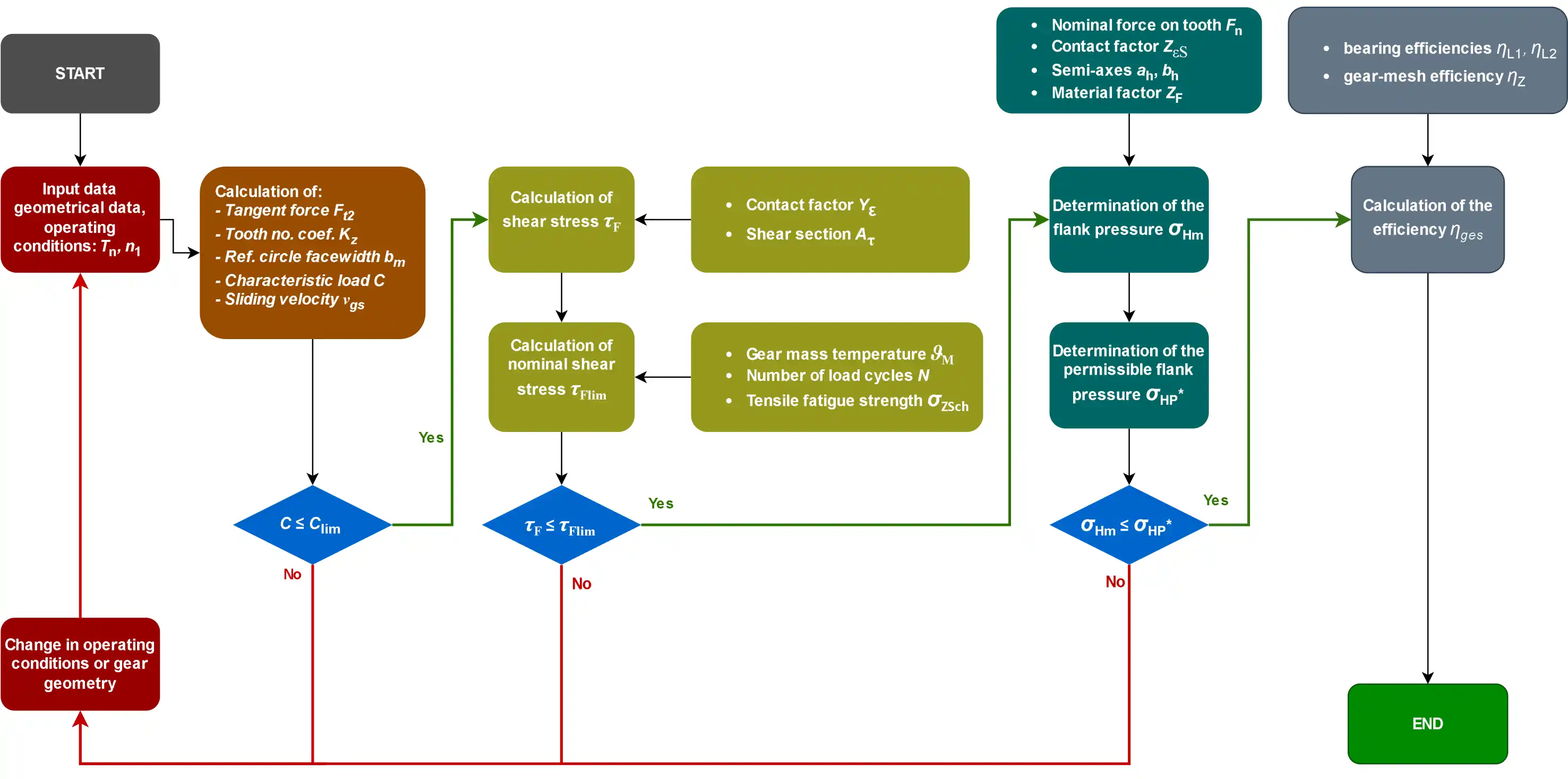
Fig. 3: Overview of the worm gear rating workflow according to the VDI 2736: Part 3 guideline (reconstructed based on the flowchart defined in [1]).
2.2.1 Tooth Root Load Carrying Capacity
The guideline presents a model for evaluating worm wheel tooth fracture load-carrying capacity. While the precursor guideline, the VDI 2545, considered bending root stress as the main fatigue failure criterion (leading to root crack induced failure), the updated 2736 guideline assumes that fracture predominantly occurs at the edge of the worm (i.e., at its addendum diameter, see Fig. 4) and considers instead the shear fatigue stress as being the one leading to this type of failure.
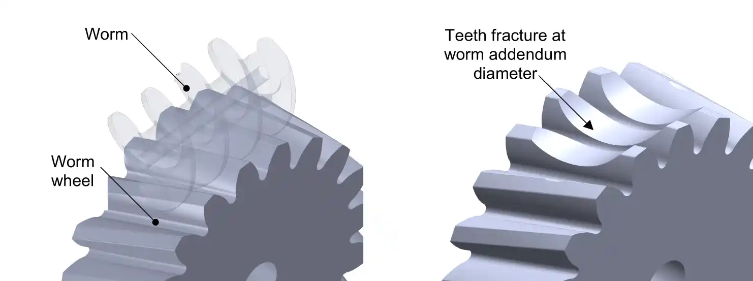
Fig. 4: Worm wheel teeth fracture at the tip (addendum) diameter of the worm gear.
According to Wassermann [9], a shear fatigue stress safety factor can be introduced as:
\[ S_{\mathrm{F}}=\frac{\tau_{\mathrm{Flim}}}{\tau_{\mathrm{F}}} \geq S_{\mathrm{Fmin}} \tag{1} \]
Here \(\tau_{\mathrm{Flim}}\) is the shear fatigue strength of the used worm wheel material, while \(\tau_{\mathrm{F}}\) is the evaluated nominal shear stress. The guideline assumes that \(\tau_{\text{Flim}}\) can be approximated as a fraction of the tensile fatigue strength at the specified operation temperature \(\vartheta_{\mathrm{M}}\) (of which data are more readily available) and recommends to multiply the tensile fatigue strength by a factor of 0.75 to obtain shear strength data. A more accurate way is to obtain the shear fatigue data directly from gear tests, which will be shown in our next article. The nominal shear stress is calculated as:
\[ \tau_{\mathrm{F}}=\frac{F_{\mathrm{t} 2} \cdot K_{\mathrm{A}}}{A_{\tau}} \cdot Y_{\varepsilon} \tag{2} \]
Here \(F_{\mathrm{t} 2}, K_{\mathrm{A}}, Y_{\varepsilon}\) and \(A_{\tau}\), are the tangential force on the wheel, application factor, contact factor, and shear section area respectively. \(A_{\tau}\) is defined as a radial projection of the fracture area as depicted in Fig. 5.
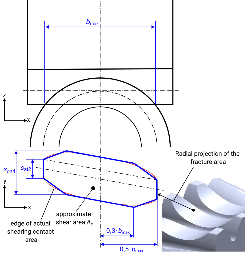
Fig. 5: Shear section area \(A_{\tau}\) used in the VDI 2736: Part 3 [1] fatigue model for nominal shear stress evaluation.
The fatigue fracture model assumes there is no major wear involved throughout the worm wheel’s life cycle, since wear would influence the shear section area. If measurable wear is identified, a reduced tooth thickness of the wheel should be considered in the calculation, in line with the expected wear rate.
2.2.2 Flank Load-Carrying Capacity
In worm gears, flank pressure is crucial for estimating the overall wheel load-carrying capacity. Hertzian theory is used to calculate this type of pressure, considering the elastic deformation of the contact area. This deformation creates an ellipsoid distribution of the compressive stress, with the maximum stress occurring approximately at the centroid of the contact area (Fig. 6).
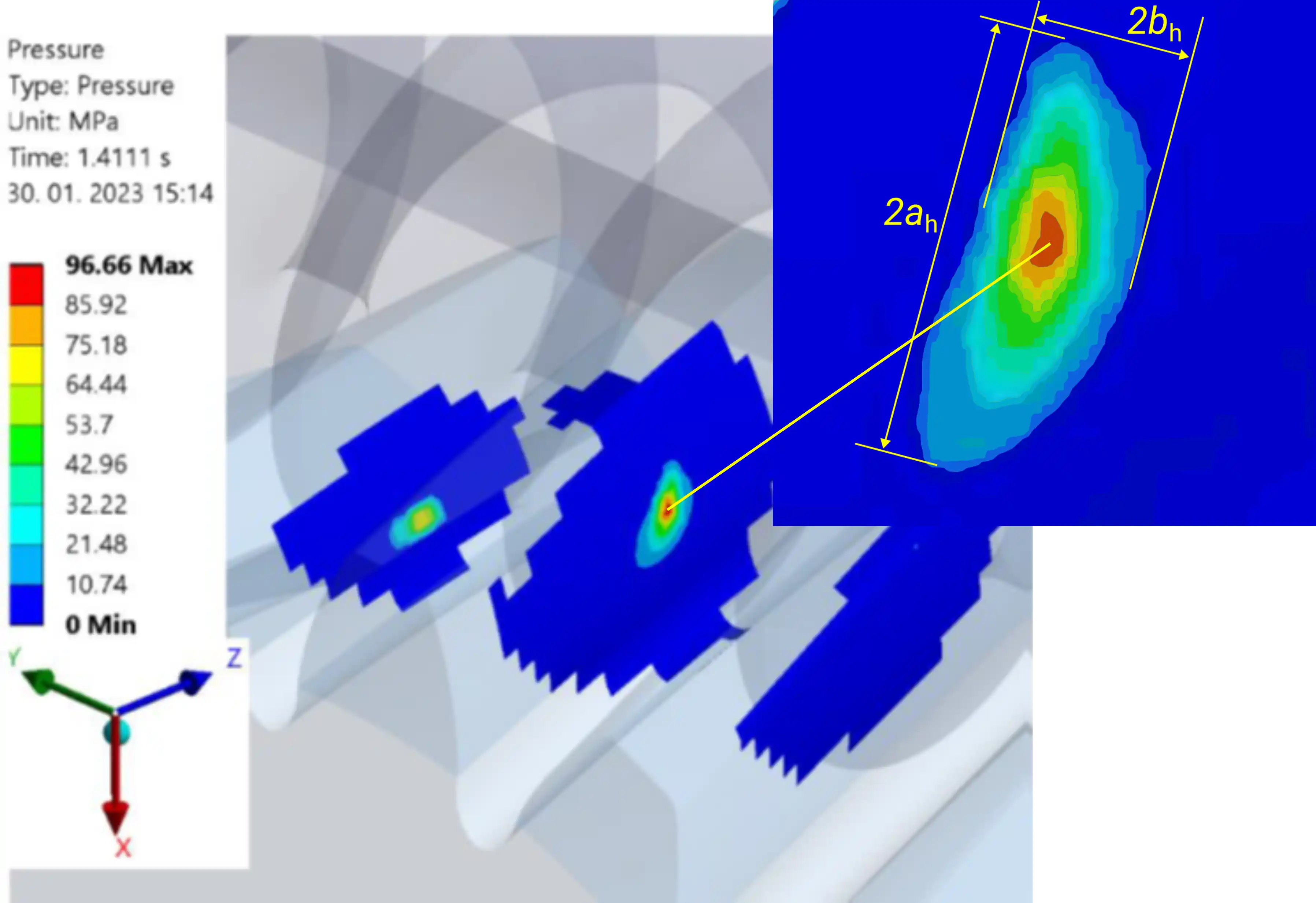
Fig. 6: Ellipsoid shape of the tooth contact at the pitch circle area as calculated using FEA on a typical plastic worm wheel geometry (the simulation was performed for a complete tooth meshing cycle using a non-linear quasi-static time-dependent contact analysis model).
Here, the flank curvature near the contact zone and the material properties of the gears influence the reached flank pressure magnitudes significantly. In line with the above, the average or nominal flank pressure is defined as [10]:
\[ \sigma_{\mathrm{Hm}}=\frac{3}{2} \cdot \frac{F_{\mathrm{n}} \cdot K_{\mathrm{A}} \cdot Z_{\varepsilon \mathrm{S}}}{\pi \cdot a_{\mathrm{h}} \cdot b_{\mathrm{h}}} \leq \sigma_{\mathrm{HP}} \tag{3} \]
where \(F_{\mathrm{n}}, Z_{\varepsilon \mathrm{S}}, a_{\mathrm{h}}\), and \(b_{\mathrm{h}}\) are the normal force, contact factor, major and minor semi-axes of the contact ellipse respectively. The limit contact stress, \(\sigma_{\mathrm{HP}}\), is typically taken from available data in the VDI 2736: Part 2 [11] guideline for cylindrical gears, which can however result in insufficient safety factors. In the subsequent section, methods for the characterization of \(\sigma_{\mathrm{HP}}\) on worm gear pairs is discussed. The normal force can be calculated as follows:
\[ F_{\mathrm{n}}=\frac{F_{\mathrm{t} 2} \cdot \cos \rho_{\mathrm{z}}}{\cos \alpha_{\mathrm{sn}} \cdot \cos \left(\beta_{\mathrm{s} 2}+\rho_{\mathrm{z}}\right)} \tag{4} \]
Here, \(F_{\mathrm{t} 2}, \rho_{\mathrm{z}}, \alpha_{\mathrm{sn}}\), and \(\beta_{\mathrm{s} 2}\) are the tangential force on the wheel, the frictional angle, normal pressure angle and the helix angle at the helix circle of the worm wheel. The contact factor is a function of the contact ratio in the normal direction
\[ Z_{\varepsilon S}=\frac{1}{\sqrt{\varepsilon_{\mathrm{n}}}} \tag{5} \]
while the frictional angle is a function of the coefficient of friction \(\mu\) and normal pressure angle:
\[ \rho_{\mathrm{z}}=\arctan \left(\frac{\mu}{\cos \alpha_{\mathrm{sn}}}\right) \tag{6} \]
The semi-axes of the contact ellipse are further:
\[ a_{\mathrm{h}}=Z_{\mathrm{F}} \cdot \xi \cdot \sqrt[3]{K_{\mathrm{A}} \cdot F_{\mathrm{n}} \cdot \rho_{\mathrm{n}}} \tag{7} \]
\[ b_{\mathrm{h}}=Z_{\mathrm{F}} \cdot \eta \cdot \sqrt[3]{K_{\mathrm{A}} \cdot F_{\mathrm{n}} \cdot \rho_{\mathrm{n}}} \tag{8} \]
and are both a function of the elastic properties of the selected material pair:
\[ Z_{\mathrm{F}}=\sqrt[3]{\frac{3}{2} \cdot\left(\frac{1-v_{1}^{2}}{E_{1}}+\frac{1-v_{2}^{2}}{E_{2}}\right)} \tag{9} \]
the equivalent radius of curvature at helix point, \(\rho_{\mathrm{n}}\), and empirically defined coefficients \(\eta\) and \(\xi\). \(\rho_{\mathrm{n}}\) is calculated using:
\[ \rho_{n 1,2}=\frac{\sqrt{d_{s 1,2}^{2}-d_{b 1,2}^{2}}}{2 \cdot \cos \beta_{b 1,2}} \tag{10} \]
with \(d_{s 1,2}, d_{b 1,2}\) and \(\beta_{b 1,2}\) being the helix and base circle diameters and the base circle helix angle of both gears in pair. \(\rho_{\mathrm{n}}\) is then evaluated as
\[ \frac{1}{\rho_{\mathrm{n}}}=\frac{1}{\rho_{\mathrm{n} 1}}+\frac{1}{\rho_{\mathrm{n} 2}} \tag{11} \]
2.2.3 Efficiency
Worm gear efficiency is in general much lower than that of cylindrical spur or helical gears. The efficiency is in effect a function of the coefficient of friction and the worm’s helix angle \(\beta_{\mathrm{s} 1}\) (or its complement, the lead angle \(\gamma_{\mathrm{m} 1}\)). If the efficiency drops below 50% the worm gear drive is said to be self-locking, meaning that it cannot run if power is applied on the worm wheel to drive the worm. Per VDI guideline, if the input power is introduced on the worm, the efficiency is calculated as:
\[ \eta_{\mathrm{z}}=\frac{\tan \beta_{\mathrm{s} 2}}{\tan \left(\beta_{\mathrm{s} 2}+\rho_{\mathrm{z}}\right)} \tag{12} \]
Alternatively, if the worm wheel is driving (assuming the pair is not self-locking), the efficiency is:
\[ \eta_{\mathrm{z}}=\frac{\tan \left(\beta_{\mathrm{s} 2}-\rho_{\mathrm{z}}\right)}{\tan \beta_{\mathrm{s} 2}} \tag{13} \]
References
- VDI 2736 - Part 3, Thermoplastic gear wheels - Crossed helical gears - Mating cylindrical worm with helical gear - Calculation of the load-carrying capacity, 2014.
- VDI 2736 - Part 1, Thermoplastic gear wheels - Materials, material selection, production methods, production tolerances, form design, 2016.
- A. Miltenovic, M. Banic, Đ. Miltenović, Load Capacity of Cylindrical Worm Gears According to DIN 3996-2012, Machine Design 9 (2017) 45-50.
- ISO/TR 14521:2010, Gears - Calculation of load capacity of wormgears.
- ISO/TS 14521:2020, Gears - Calculation of load capacity of worm gears.
- P.E. Schnetzer, J. Pellkofer, K. Stahl, Calculation method for wear of steel-bronze rolling-sliding contacts relating to worm gears, Forsch Ingenieurwes 87 (2023) 961-971.
- ISO 10828:2024, Worm gears - Worm profiles and gear mesh geometry.
- VDI 2545 - Gear wheels made from thermoplastics, 1981.
- J. Wassermann, Einflussgrößen auf die Tragfähigkeit von Schraubradgetrieben der Werkstoffpaarung Stahl/Kunststoff, Diss. Ruhr-Universität Bochum, 2005.
- S. Oberle, Tragfähigkeit und Ausfallursachen von Kunststoffzahnrädern, Tagungsband Maschinenelemente aus Kunststoff, Lehrstuhl für Kunststofftechnik (LKT) der Universität Erlangen, 2008.
- VDI 2736 - Part 2, Thermoplastic gear wheels - Cylindrical gears - Calculation of the load-carrying capacity, 2014.