Powertrain & Gear Testing
Robotic drive test rig
Overview
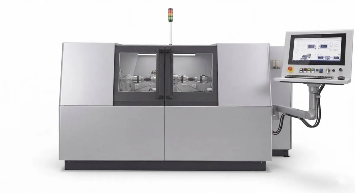
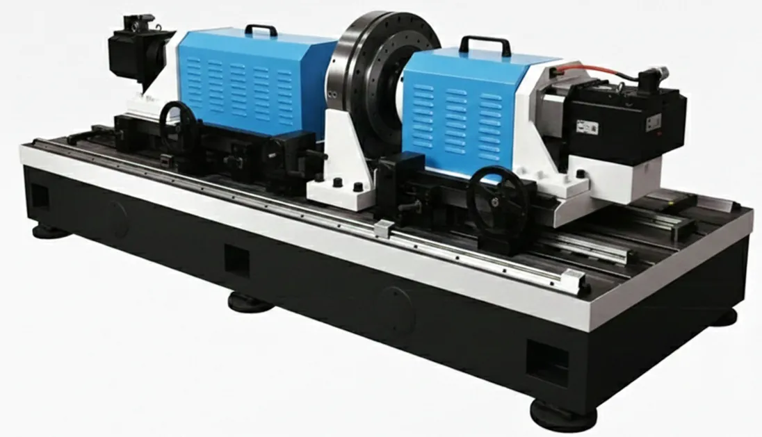
The robotic drive test rig is a custom-built test bench for coaxial gear
drives – planetary gearboxes and precision reducers used in robotics applications. It is
designed for lifetime and performance testing of the complete drive unit: input (drive) and
output (brake) power are provided by electrically controlled drive and brake motors, applying
controlled speed and torque on both sides of the tested drive while the parameters that matter
for robotic joints are
measured – durability, backlash, transmission error and NVH behaviour. The platform is
available in two configurations: an R&D-oriented version for flexible laboratory testing and
an automated end-of-line version for production testing.
1 / 2
2 / 2
❮
❯
Two configurations
R&D and end-of-line versions
Version 1
R&D testing
A self-standing rig for research and development. The tested drive is mounted
manually and run through flexible load regimes for lifetime evaluation, prototype validation and
design optimisation.
- Manual mounting and operation
- Constant load, load spectra and time-varying regimes
- Full instrumentation for R&D data acquisition
- Interchangeable mounts for various drive geometries
Version 2
End-of-line testing
An automated configuration for production – e.g. end-of-line assembly
testing. The rig is upgraded for automatic handling and a defined array of pass/fail testing
functionalities, tailored to the specific assembly and line requirements.
- Automated (end-of-line) assembly testing
- Defined pass/fail test functionalities
- Configured around your assembly and cycle time
- Major upgrade – scoped to your application
Preorder inquiry
Interested in the robotic drive test rig? Tell us about your drive and testing
requirements and we'll get back to you within 24 hours with configuration options and a quote.
Features and specifications
The drive side positions axially to accommodate different gearbox widths, and
adaptable input/output connectors together with an interchangeable test-drive mount let the rig accept
a range of coaxial drive geometries. All critical sensing equipment ships with calibration
certificates, and the electronics, data acquisition and safety systems are included. The rig is
operated from a regular Windows PC or laptop over an Ethernet connection to the test rig.
Testing capabilities
- Lifetime testing of planetary gearboxes and precision reducers
for robotics
- Constant load and load-spectra testing
- Predefined time-varying load operation regimes
- Coaxial (fully aligned) input and output axes
Drive and load system
- Input (drive) and output (brake) power via electric motor control
on drive and brake sides
- Input and output rotational speed measurement
- Axial positioning of the drive side for mounting and various
drive geometries
- Adaptable input and output side connectors to the tested drive
- Interchangeable test-drive mount for various drive geometries
Control and software
- Dedicated software for data acquisition, visualization and
storage (Windows OS compatible)
- Operated from a regular Windows PC or laptop
- Ethernet communication with the test rig
- Optional industry-grade PC integrated into the rig for
independent control and analysis1
Safety and compliance
- Self-standing rig with integrated safety equipment
- Safety features in line with relevant EU machinery directives
- Calibration certificates for all critical sensing equipment
- Power supply: 220 VAC or 400 VAC depending on the final
configuration
Included
- Electronics, data acquisition and safety equipment
- Measurement, visualization and storage software
- Calibration certificates for critical sensors
- Interchangeable mounts and drive-side connectors
Specifications
Representative base configuration – the rig
is custom-built and specifications are tailored to each application.
| Parameter |
Specification |
| Input torque |
0.5 – 20 Nm |
| Input speed |
3000 – 25 000 rpm |
| Output torque |
30 – 2000 Nm |
| Output speed |
80 – 6000 rpm (dependent on output torque) |
| Center distance |
0 mm (coaxial – fully aligned input/output axes) |
| Axial positioning range |
Per requirement |
| Load application |
Constant load, load spectra, time-varying regimes |
| Drive / brake |
Electric motor control |
| Data acquisition & software |
Included (Windows OS compatible) |
| Communication |
Ethernet to Windows PC / laptop |
| Power supply |
220 VAC or 400 VAC (configuration dependent) |
1 On request, an industry-grade PC can be
integrated into the test rig for independent device control and data analysis. Additional costs
apply.
Add-ons
Additional modules
The rig can be extended with optional modules that add thermal, NVH, backlash and
transmission-error testing, as well as full production-line automation. Modules can be ordered with the
rig or retrofitted later.
A. Temperature control modules
- A.1 Elevated temperatures – surrounding
air controlled between ambient and 100 °C; tested drive unit between 40 °C and
120 °C
- A.2 Cryogenic to elevated temperatures –
surrounding air controlled between −40 °C and 100 °C; tested drive unit
between −40 °C and 120 °C
- Requires an additional thermal chamber and tempering system
B. NVH diagnostics
- B.1 Vibration measurements – detects
increases in vibration at a selected location; multiple accelerometers can be installed (incl.
Dewesoft DAQ and 2 calibrated piezo accelerometers)
- B.2 Noise measurements – detects
increases in noise at a selected location; multiple microphones can be installed (incl. DAQ and a
calibrated laboratory condenser microphone)
- B.2.2 Anechoic chamber upgrade –
minimizes echoes and insulates the drive for absolute noise-emission measurements
- NVH data acquisition and basic analysis software included
C. Backlash evaluation module
- One side is fully fixed while the other is rotated, measuring
rotational angle and applied torque
- Produces backlash “hysteresis” curves (torque vs.
angle)
- High-resolution rotary encoder, DAQ module and retention
adapters included
D. Transmission error evaluation module
- Transmission error measured by comparing rotary-angle signals on
input and output shafts (accounting for the exact gear ratio)
- High-resolution rotary encoders on drive and brake sides
- DAQ module and analysis software included
- Modules B, C and D share the same DAQ module and related
electronics – ordering several together reduces the overall price.
E. Testing automation module (end-of-line)
- Upgrades the rig for automated (e.g. end-of-line) assembly
testing
- A major upgrade, highly dependent on the assembly and the
selected array of testing functionalities
- Scoped and quoted per application
Delivery lead time is typically 6–8 months after order confirmation, depending on the ordered
modules and current component lead times. Lifetime service support (maintenance, recalibration and
upgrades) is provided. Contact us for current pricing, module bundles and lead times.